EMI Filter
Leave a message
Electromagnetic interference filter (EMI Filter) is a new type of composite device which has been widely used in recent years. The utility model can effectively suppress the noise of the power grid, improve the anti-interference ability of the electronic equipment and the reliability of the system, and can be widely used in the fields of electronic measuring instruments, computer room equipment, switching power supply, measurement and control systems, etc..
EMI Filter - New Moon - New Moon
1 the principle and application of electromagnetic interference filter
1.1 structure principle
EMI Filter - New Moon - New Moon
Power supply noise is a kind of electromagnetic interference, the spectrum of the conduction noise is about 10kHz ~ 30MHz, up to 150MHz. According to the direction of transmission, power supply noise can be divided into two categories: one is from the power supply into the line of the introduction of external interference, and the other is generated by the electronic equipment and the power line transmission to the noise. The results show that the noise belongs to the bidirectional interference signal, and the electronic equipment is not only the object of noise jamming, but also a noise source. According to the characteristics of formation, there are two kinds of noise interference, the series mode interference and common mode interference. The series mode interference is the noise between two power lines. Common mode interference is the noise of the two power lines to the earth. Therefore, the electromagnetic interference filter should meet the electromagnetic compatibility (EMC) requirements, must also be a two-way RF filter, on the one hand to external electromagnetic interference filtering from the AC power line is introduced, on the other hand can avoid the equipment itself outside noise interference, so as not to affect the normal work of other electronic equipment in the same electromagnetic environment. In addition, the EMI filter plays an inhibitory role on the series mode and common mode interference
1.2 basic circuit and its typical application
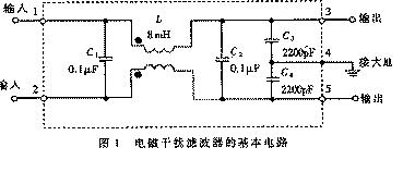
The basic circuit of EMI filter is shown in figure 1.
EMI Filter - New Moon - New Moon
The five terminal device has two input terminals, two output terminals and a grounding terminal. Including the common mode choke circuit (also known as the common mode inductor and filter capacitor C1) L ~ C4. L had no effect on serial mode interference, but when the common mode interference due to the magnetic flux direction two coils of the same, after the total inductance coupling increases rapidly, so the common mode signal showing great inductance, not easy to pass, so called common mode choke. Its two coils are wound in ferrite of low loss, high permeability, when a current passes through the magnetic field on the two coils will reinforce each other. The inductance of the L is related to the rated current I of the EMI filter, as shown in table 1. Needs to be pointed out that when the rated current is large, the common mode choke diameter will increase accordingly, in order to be able to withstand large current. In addition, the low frequency attenuation can be improved by properly increasing the inductance. C1 and C2 use a thin film capacitor, the capacity range is roughly 0.01 F ~ ~ 0.47 F, mainly used to filter out the interference. C3 and C4 are connected to the output, and the neutral point of the capacitor is grounded, which can effectively restrain the common mode interference. C3 and C4 can also be connected in parallel at the input end, still choose ceramic capacitors, the capacity range is 2200pF ~ 0.1 F. In order to reduce the leakage current, the capacitance should not exceed 0.1 F, and the middle point of the capacitor should be connected with the earth. C1 ~ C4 pressure resistance value is 630VDC or 250VAC.
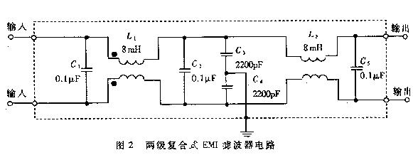
Figure 2 shows a kind of internal circuit of the two stage compound EMI filter, because of the use of the level two (also called two) filtering, so the effect of filtering noise is better. For some users there are thousands of Hz repetition frequency of fast transient pulse group interference, both at home and abroad have also developed group pulse filter (also known as the group is able to counter pulse), inhibition of the disturbance.
Application of 2 EMI filter in switching power supply
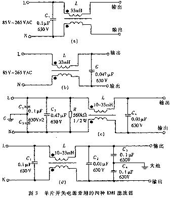
In order to reduce the volume and reduce the cost, the single chip switching power supply usually adopts the simple single stage EMI filter, which is shown in the typical circuit 3. Figure (a) and figure (b) in the capacitor C can filter out the interference, the difference is only C (a) will be connected to the input end, figure (b) is connected to the output. Figure (c), (d) shows that the circuit is more complex, interference suppression effect is better. Figure (c) in the L, C1 and C2 used to filter out the common mode interference, C3 and C4 filter interference. R is the discharge resistance, the charge on C3 accumulation release, to avoid the charge accumulation and effect of filter characteristics; power line can make the end L and the power of N is not charged, ensure the safety of use. Figure (d) is the common mode interference filter capacitor C3 and C4 connected to the output.
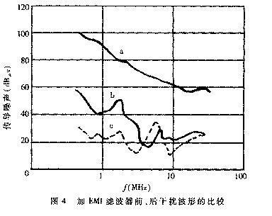
EMI filter can effectively suppress the electromagnetic interference of single chip switching power supply. Figure 4. The curve of 0.15MHz ~ 30MHz conduction noise in switching power supply (EMI), which is the curve of a in the switching power supply (i.e. the peak envelope of electromagnetic interference). Curve B is inserted as shown in Figure 3 (d) EMI filter waveform, the electromagnetic interference can be attenuated 50dB V ~ 70dB V. Obviously, the effect of this EMI filter is better.
For some users there are thousands of Hz repetition frequency of fast transient pulse group interference, both at home and abroad have also developed group pulse filter (also known as the group is able to counter pulse), inhibition of the disturbance.
Application of 2 EMI filter in switching power supply
In order to reduce the volume and reduce the cost, the single chip switching power supply usually adopts the simple single stage EMI filter, which is shown in the typical circuit 3. Figure (a) and figure (b) in the capacitor C can filter out the interference, the difference is only C (a) will be connected to the input end, figure (b) is connected to the output. Figure (c), (d) shows that the circuit is more complex, interference suppression effect is better. Figure (c) in the L, C1 and C2 used to filter out the common mode interference, C3 and C4 filter interference. R is the discharge resistance, the charge on C3 accumulation release, to avoid the charge accumulation and effect of filter characteristics; power can make the power supply