Switching power transformer
Leave a message
Switching power transformer

Switching power transformer is a power transformer with switching transistor. In addition to the voltage conversion function of ordinary transformer, it also has the function of insulation isolation and power transmission, which is commonly used in switching power supply and other occasions involving high-frequency circuits.
The main material of switching power transformer: magnetic material, wire material and insulation material are the core of switching power transformer.
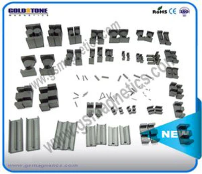
Magnetic Material: The magnetic material used in switching transformers is soft ferrite, which can be divided into MnZn series and NiZn series according to its composition and application frequency.
Wire Material-Enameled Wire: Enameled Wire for winding small electronic transformer generally has two kinds of high-strength polyester enameled wire (QZ) and polyurethane enameled wire (QA). According to the thickness of enameled layer, it is divided into 1 type (thin enameled wire) and 2 type (thick enameled wire). The insulating layer is polyurethane paint, with strong self-adhesive, self-welding performance (380 C), can be directly welded without removing the paint film
Pressure-sensitive tape: insulating tape has high resistance to electricity, easy to use and good mechanical properties. It is widely used in interlayer, group insulation and outsourcing insulation of switching transformer coils. It must meet the following requirements: good viscosity, peeling resistance, certain tensile strength, good insulation, good voltage resistance, flame retardant and high temperature resistance.
Skeleton Material: Switch transformer skeleton is different from ordinary transformer skeleton. Besides being the insulation and supporting material of coil, it also takes the role of fixing and locating the whole transformer. Therefore, the skeleton material should not only meet the insulation requirement, but also have considerable tensile strength, and also bear the welding resistance of pins. Thermal deformation temperature of skeleton material is higher than 200 C. The material must be flame retardant, and it should be processed well and easy to be processed into various shapes.
Fold edit paragraph detection method
1, check the appearance of the transformer to see if there is any obvious abnormality. Such as whether the coil lead is broken, desoldering, insulation material whether there is burning mark, iron core fastening screw is loose, silicon steel sheet is rusty, winding coil is exposed and so on.
2. Insulation test. Measure the resistance between the core and the primary, the primary and secondary, the core and the secondary, the electrostatic shielding layer and the secondary and secondary windings with the multimeter R 65 Otherwise, the insulation performance of the transformer is poor.
3, the detection of the on-off of the coil. If the resistance of a winding is infinite, it shows that the winding has a breaking fault.
4. Distinguish primary and secondary coils. The primary and secondary pins of the power transformer are usually drawn from both sides, and the primary winding is more than 220 V, and the secondary winding is marked rated voltage, such as 15V, 24V, 35V. Then identify them based on these markers.
5. No load current detection
A, direct measurement. All the secondary windings are all opened, and the multimeter is placed in an alternating current block (500mA), which is connected to the primary winding. When the plug of the primary winding is inserted into 220V AC power, the no-load current value is indicated by the multimeter. This value should not be greater than the 10%~20% of the transformer full load current. The normal no-load current of power transformers in common electronic equipment should be around 100mA. If it goes too far, it indicates that the transformer is short circuited.
B and indirect measurement. In the primary winding of the transformer, a 10? /5W resistor is connected in series, and the secondary parts are still empty. Dial the multimeter to the AC voltage barrier. After power-on, the voltage drop U at both ends of resistance R is measured with two meter pens, and then the no-load current I-space, i.e. I-space = U/R, is calculated by Ohm's law. F? No load voltage detection. The no-load voltage values (U21, U22, U23, U24) of each winding measured successively with a multimeter AC voltage connection should meet the requirements. The allowable error ranges are generally: high-voltage winding < 10%, low-voltage winding < 5%, and the voltage difference between the two symmetrical windings with a central tap < 2%.
6. The allowable temperature rise of small power transformer is 40 ~50 ~C. If the insulating material is good, the allowable temperature rise can be improved.
7, detect and identify the same name ends of each winding. When using a power transformer, sometimes two or more secondary windings can be used in series in order to obtain the required secondary voltage. When power transformer is used in series method, the same name terminals of each winding in series must be connected correctly and can not be mistaken. Otherwise, the transformer will not work properly.
8. Comprehensive detection and discrimination of short circuit faults of power transformers. The main symptoms of short-circuit fault of power transformer are serious fever and abnormal output voltage of secondary winding. Usually, the more inter-turn short-circuit points in the coil, the greater the short-circuit current, and the more serious the transformer heats. A simple way to detect and determine whether a power transformer has a short-circuit fault is to measure the no-load current (as described earlier). The transformer with short circuit faults will be far less than the 10% of full load current. When the short circuit is serious, the transformer will quickly heat up within tens of seconds after no-load power-up. Touching the iron core by hand will make the transformer feel hot. At this time, no load current can be measured, and it is concluded that there is a short-circuit point in the transformer.
If you have any interest in our products ,please contact us:
FAX:86-29-85401274 Mobile:153 5351 3263
Email:sales@gsmagnetics.com sales@gstronics.com
Contact person :Mr Mark Chen(General Manager)
Skype: Mark.chen90