

Winding Process Of Electronics Transformer
Leave a message
Winding process of electronics transformer
Many engineers are not sure about the winding process of the transformer, which leads to repeated debugging of the product to meet the initial design parameters. Transformer process design involves a lot of things, this post discusses the various winding process on the power supply parameters.
If you want to design the transformer well, you need to choose the transformer first.
The choice of transformer is restricted by many factors.
First, we need to calculate the Ap value of the transformer as follows:
Ap= Aw*Ae= (Pt*10^4) / (2 B*fs*J*Ku)
Ap: transformer power capacity
Aw: core window area
Ae: cross section of magnetic core.
Pt: transfer power of transformer (Pt = Po / +Po)
B: the change of magnetic flux density (usually 0.2-0.3)
FS: working frequency of magnetic core
J: current density (self cooled 4-6, air cooled 6-10)
Ku: Copper fill factor of window (usually 0.2-0.5)
After getting the Ap value, we have to choose the transformer according to the structure size of the power supply, including the height, width and length of the transformer.
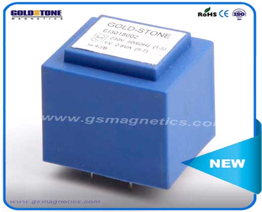
When the overall height of the power supply is limited, it is necessary to consider the flat transformer, horizontal transformer is the preferred. Common EE series, EC series, ER series horizontal transformer, EF series and EFD series transformer; if the ultra-thin adapter and LED fluorescent lamp built-in power supply, can consider the plane transformer.
If PCB space is limited, you should choose PQ, RM, or canned cores, because these cores have large cross-sectional area, occupy less space, and can output more power.
Secondly, in the selection of transformers, we should choose different transformers according to the different parameters and emphasis of the circuit.
For example, in flyback power supply, we hope that the smaller the leakage inductance, the better, because the leakage inductance will affect the voltage and current stress of power devices, and also has an impact on EMC can not be ignored, then we look for transformers which are beneficial to leakage inductance control, such as PQ, RM, and ERL transformers, plus a reasonable winding method. The leakage inductance can be controlled below 3%.
For example, LLC power supply, we want to use transformer leakage inductance as resonant inductance, so we need to deliberately increase the leakage inductance, choose slotted skeleton to winding more ideal.
Thirdly, when choosing the transformer, the cost and versatility should be taken into account.
Cost is not only the concern of every business owner, but also the most entangled problem of our R&D engineers. Unless it is a small number of military grade or high-grade power supply regardless of cost, we should find a balance between performance parameters and cost in design, and do not deliberately pursue a certain parameter and ignore the belt. The impact of the cost, sometimes even if each transformer increases the cost of a few cents, if batch up, is an expense can not be ignored.
Unless business considerations are taken into account, it is hoped that its products will not be copied by other manufacturers. Private-mode or bias-gate transformer cores and frameworks are generally not considered, because the supply channels and cycles will be greatly constrained when mass production occurs, while common cores, whether in price or in supply channels and cycles. They all have great selectivity.
Contact Us
If you have any interest in our products ,please contact us:
FAX:86-29-85401274 Mobile:153 5351 3263
Email:sales@gsmagnetics.com sales@gstronics.com
Contact person :Mr Mark Chen(General Manager)
Skype: Mark.chen90